Hasegawa 1/72 MiG-23S Flogger-B

| I've always been fascinated by the MiG-23, and it was disappointing to learn that it was a bit of a dog. But the fascination remained: I think I have all MiG-23 models that exist in 1/72 scale, except the very rare YuMTK model. My first one was the good old Hasegawa kit from 1977. Although completely overtaken by modern MiG-23 kits, I decided to build it, not as a standard model, but as a test bed for the corrections required to rectify the worst shape problems. That's a skill that I've been working on for a long time. The modifications will also give a better understanding of the MiG-23 shape, and allow me to judge the other MiG-23 models better. I will not spend time on details, it's the shape that I want to get right. If you want the details to be right too, it's much easier to build a modern MiG-23 model, instead of this oldie.
|
Subconscious motivation
About halfway the build process I realised something. Way back, I used to buy various modeling magazines, like Modell Fan, Fine Scale Modeler, Scale Models / Scale Models International and Kit (but not all issues, far from it!). A small number of articles in those magazines left a lasting impression.
One of them was the June 1988 issue of Scale Models International, that featured an article by Graham Napper on correcting the then-new Hasegawa 1/72 MiG-29, with considerable plastic surgery. I remember that I was very, very impressed by such advanced modeling. I read it multiple times to absorb all the techniques, and tried to see the details in the grainy black and white photos.
| 
|
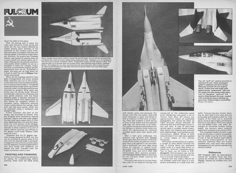
| And here I am, thirty years later, doing the same thing, but on a MiG-23 instead of a MiG-29! Since I realised these similarities, I'm enjoying this project even more.
|
The model
Scalemates lists the Hasegawa 1/72 MiG 23S as being issued in 1977. As far as I can see, the MiG-23 hadn't visited the West at that point. A year later, six Kubinka-based MiG-23MLs visited Finland, at Kuopio-Rissala air base, between 1st and 4th of August. The same six aircraft visited France, at Reims air base in September. IPMS Finland published drawings in its IPMS-Mallari magazine, issue 1/1979. Therefore the kit was most likely developed with Hasegawa's own research. Scale Models, January 1980, had an article on the Hasegawa kit to improve it. The article list just four references: Air International December 1978, Aviation News October 13/26 1978, Flight International December 1978, and lastly the book Soviet Aircraft Of Today. This gives a good impression of the limited references available at that time.
My box is a 1987 issue according to Scalemates, and it reads 'MiG-23S Flogger-B'. That combination is incorrect: the MiG-23S was the Flogger-A with a different engine, tail surfaces placed more forward and a conical radome. The Hasegawa model looks like a MiG-23M/MF Flogger-B in all aspects.
I did not have a fixed plan when I started working on this model. There were no examples to follow, I do not know of a single report of a completely modified / corrected Hasegawa 1/72 MiG-23. However I did find some reviews that have some information on shape problems:
Construction
In this photo you can see two modifications that I tried on the front fuselage. Firstly, I measured a MiG-23ML photo (the best I had at the time) and made the radome accordingly bulkier. I added 0.4 mm diameter on the radome division line (that is in the wrong place). On the radome side, I wrapped an 0.2 mm plastic strip all around. On the fuselage side, I glued an 0.4 mm plastic strip to the top side, that tapered to 0.2 mm on the sides. It had the effect of slightly raising the radome, mainly to reduce the slope between the windshield and the radome.
Secondly, I wanted to have the canopy sill almost horizontal, with the added benefit of a reduced fuselage height. The wedges that I cut out are 50 x 2 mm, and the fuselage could be bent quite easily. The fuselage is now 21.0 mm high at the connection to the mid-fuselage.
| 
|

| I superglued the open wedges together. I then decided to assemble the whole front fuselage, even though there is no cockpit interior or nose landing gear well. For the sake of science, so to say. I used Mr Surfacer to smoothen things, then scribed a panel line at 28.5 mm aft of the radome nose, following the 4+ drawings.
I photographed the modified front fuselage and an unmodified Hasegawa front fuselage, glued to a piece of plastic card, to show the shape changes.
As you can see, I moved the radome panel line aft quite a lot, compared to the Hasegawa panel lines. The latter are some 3 mm too far forward. And mine is about 2 mm too far aft for an M/MF, since I used a photo of an ML. Back then I did not know the ML had a larger radome - see the Appendix for that.
|
Here's another comparison of the two noses. The modified front fuselage is now 21.0 mm high at the connection to the remainder of the fuselage.
A side effect of bulking up the radome is that the radome width is 0.5 mm larger than that of the cockpit section. It reminds me of the Sukhoi 15 shape. Whether it's correct or wrong I don't know yet.
| 
|

| The next problem was how to fit the lowered cockpit section to the fuselage. It looked like a difficult problem to solve, since the center fuselage is 22.7 mm tall at the front. Where to remove the 1.7 mm difference? Then I noticed that the spine was also too tall. Measuring from the 4+ drawings, I concluded the spine was 1.5 mm too tall at the front of the fuselage, and 1 mm too tall at the wing pivot position. I removed those amounts of material locally as a test. To my surprise, this already made the two parts agree in height.
|
| To allow the removal of the spine, I glued a 1 mm plastic card inside the top fuselage half. I curved it slightly to fit the fuselage properly. On top of that I glued a 2 x 1 mm strip to support the hinges of the wing halves.
| 
|

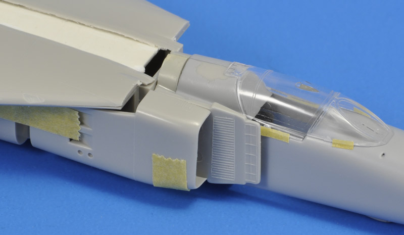
| According to other analyses, an extension of 4 mm is required at the joint, to solve another shape problem of the kit. My first test fits on the 4+ drawing indeed showed that 3 to 4 mm is missing there. I sawed the rear 4 mm off an Academy MiG-23 nose section, and glued between the fuselage parts. It's lightly smaller, showing that the Academy kit is not a 100% copy of the Hasegawa. Also, the spine has been ground off.
An alternative and more interesting explanation of the size difference between the Hasegawa and Academy kits could be that Academy cut their molds using the Hasegawa kit, but forgot to compensate for the shrinkage when the plastic cools down from injection molding temperature down to room temperature. A similar 'problem' occured when Revell copied Monogram's 1/48 B-17 model (see Thomas Graham's Monogram book, page 109). Omnexus reports for High Impact Polystyrene (HIPS) minimum and maximum values of 0.20% and 0.80%. Let's take the average, 0.5% - it's not very impressive. Therefore this doesn't appear to be the correct explanation.
|
| The inlets will probably move forward with the cockpit section. It will leave some interesting gaps to be filled. The detailing on the splitter plate will either have to go, or be updated.
| 
|

| A bit of a wild modification was to tuck in the fuselage sides forward of the main landing gear wells. I read that the Hasegawa model lacked a bit of 'coke bottle' effect behind the intakes. I sawed through the part in multiple places, leaving the fuselage side itself intact to serve as a hinge. I chose to tuck in the sides to the amount of the fuselage wall thickness, about 1 mm. That created near-straight sides of the fuselage.
|
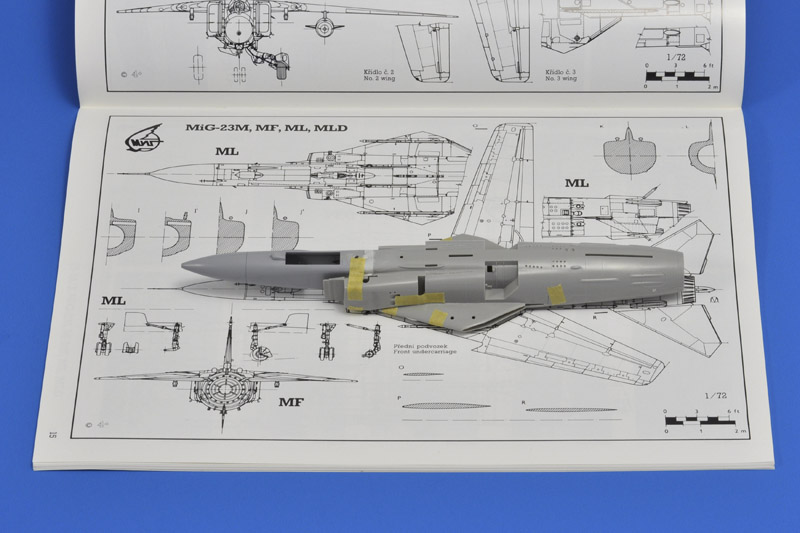
| The model now fits well on the 4+ drawing. You can also see the 'Coke bottle' effect of the modified intake ducts - they have been tapered towards the rear to make them meet with the now narrower fuselage.
| 
|

| In this photo both inlets have been glued on and treated with (mostly) Mr Surfacer 1000 from a bottle. I used pieces from an Academy MiG-23 to fill the gaps in the inlet ducts. Strangely these were 2.5 mm whereas I moved the splitter plates close to 4 mm forward.
Compared to the 4+ drawings, the inlets should have tapered more strongely, arriving at the mid fuselage width just behind the auxiliary inlets. The kink (or transition) should have been some 5 mm more forward.
|
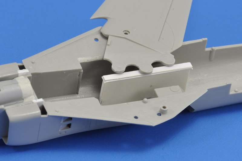
| Six photos up you can see that I added a guide strip to the top fuselage reinforcement plate, to create level wings. Only later I realised that the MiG-23 had 4 degrees of anhedral. I therefore removed the guide, and built a new guide on the bottom fuselage half. Next, I added 0.3 mm strips on the guide until the required anhedral was achieved.
| 
|

| To make the wings fit with the 4 degree anhedral, I had to sand the top side of the teeth (see above). I probably created that interference myself by gluing the backing plate to the top fuselage, before removing the spine.
|
| Here's the lower fuselage with Mr Surfacer hiding most of the crimes. The area still needs more work to make it perfect.
| 
|

| Because I did not know yet in what configuration I will build the model, I decided to install the nose gear wheel well. It's interesting that it lacks the deeper wheel well part at the rear side. But no-one from the West had seen a MiG-23 up-close at the time the model was designed.
|
| I built up the new but lower spine using plastic card edged with 0.3 mm steel wire, and started to build up the shape with Apoxie. Steel wire is employed to keep the edges straight during sanding and shaping. The job is roughly 1/3rd done here.
| 
|

| Here the job is nearly done. I ripped off the 0.3 mm spring steel wires about halfway, since they created too much of a 'square' edge to the spine. In their place I glued Albion 0.1 mm nickel silver wire, and that solved the problem.
|
After installing the nose gear bay, I finally decided to build the model gear-up, in-flight. That meant that the six doors of the main landing gear also had to be installed. That surely was a fiddly job, but the Hasegawa quality made sure the doors fitted well, only minor adjustments were required. I cut away part of the wheel wells from the inside, to have better access to position the doors accurately.
To achieve engraved panel lines around the doors that matched the other panel lines, I chamfered the edges of all parts before installation. That technique worked well. Later I realised that the kit's upper doors were actually two doors each; you can see the division as a faint line in the photo. Therefore I scribed an extra panel later after shooting this photo.
The modifications had erased many of the raised panel lines. I decided to extend the experiment by removing all raised panel lines, leaving only the few engraved panel lines. Maybe I will re-apply the panel lines with light pencil lines.
| 
|

| For the in-flight posing, I installed a 2 mm plastic tube with 1 mm internal diameter, just ahead of the ventral fin. You can see the bottom end in the previous photo. It was further strengthened by triangular pieces of 1 mm plastic card, that were glued to the wing sweep anhedral support.
Also visible are the partly cut out wheel wells, to assist in the installation of the many doors. I filled the wells with Apoxie epoxy clay to strengthen the delicate doors.
|
| Likewise the doors of the nose landing gear were fitted, using the same techniques as with the main landing gear doors.
| 
|
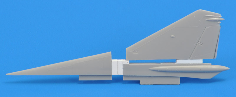
| The last major surgery involved the vertical tail. I held the Hasegawa part on the 4+ drawing, and decided to cut the part in three pieces. I cut off the front piece at the kink in the leading edge. The remaining part was cut on the extended line established by the rudder's lower side. I glued a 1.5 mm high spacer at the front, and a 2 mm high spacer at the rear, and reglued the rear two parts. The upper part was set back 1 mm, and I noted I would need to cut the rudder's trailing edge, to 1 mm at the bottom. Lastly I glued a 5 mm spacer between the front and rear parts.
|
| The new vertical tail after lots of puttying and sanding, as good as new :-) The only thing missing now are the raised panel lines.
| 
|

| The pylons on the wing roots were more forward 2 mm, to bring them more in agreement with the 4+ drawings. However the launcher rail is still ~5 mm too short. I decided not to correct that, to keep the focus on correcting the overall shape problems.
I also decided to 'mount' the pylons using magnets. Room inside the wing glove was limited because of the sweeping wing, therefore I used 1x1 mm magnets at the rear, and a bigger 2x2 mm magnet at the front. The pylon itself only had room for 1x1 mm magnets.
|
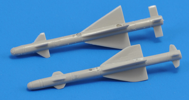
Hasegawa's R23 is not very accurate. I modified all three wing sets to match the 4+ drawing. The front wings are too far aft, but I left that. The missile bodies had various engraved details, but I had no idea what they represented. In the end removed most of them. There also are large ejector pin markings to get rid of. The missile body diameter is too large, at ~3.5 mm instead of 2.8 mm (200 mm in 1 to 1 scale).
I installed 2x2 mm magnets in the R23 bodies, and 1x1 mm magnets in lower sides of the pylon / launch rail. This combination gives a sufficiently large attraction force to keep the missile on the pylon.
| 
|

| The gun pod lacked 5-6-7 mm in length, and most of that at the rear end. I added a clump of Apoxie at the rear and sanded it into shape. What you see here is just the first step in creating the new shape.
|
| Here's the gun pod sanded to shape, and painted with Mr Surfacer from a spray can. Due to carelessness I broke off the gun tubes, so these were replaced by 0.5 mm steel wire. The pod attaches via magnets, like all other stores. This is more of an experiment than something useful. I'm actually pretty sure I will lose the gun pod one day..
| 
|
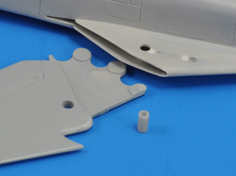
| Until now I had no solid plan what to do with the wings. Install them like Hasegawa tells you to, sandwiching them between the two fuselage halves? Or cut a slot in the wing, leading to the pivot point, so the wings could be mounted afterwards, like I tried on my Italeri Su-24? The latter was appealing, but would eliminate the wing sweeping. Luckily my modeling friend Eric Verschuur suggested another solution, that I had never seen before. On his 1/144 MiG-27 model, he had drilled out the original integral pivot pins, and made removable pins instead. That sounded like a great plan.
I drilled out the 2.5 mm diameter pivots on the lower wing root from the inside. I left the moulded 1 mm pins on the upper wing root. The new tubular pivot pins nicely slid through the lower wing root and the wing itself, and centered on the pin on the upper wing root. Note that my pivot pins are still too long. Note also that this plan could not have worked if I hadn't moved the pylons forward, and filled the original mounting holes (see the white discs).
|
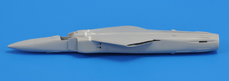
With the wing problem solved, I could finally glue the main fuselage parts together. The joint behind the cockpit could now be sorted out, hopefully the last joint that requires extensive filling with Apoxie and Mr Surfacer. The rear fuselage joint required aggressive sanding to make things smooth, so all raised panel lines were lost.
Then I had to fiddle some more with the wings, since both wing gloves would split open when the wings were moved to certain sweep angles. More scraping, sanding and lots of CA glue solved that. I still have to be careful when playing with the wings.
One drawback of having movable wings is that the opening in the wing root must be large enough for all wing positions. In other words, the gaps are larger than I would have liked. But I decided to accept this.
| 
|

| I remembered reading that something was wrong with the speedbrakes. The 4+ drawing showed the problem: Hasegawa made all four speedbrakes similar rectangles that are chamfered on all four corner. But in reality only the rear side of the lower speedbrakes are chamfered, and the top speedbrakes are shorter.
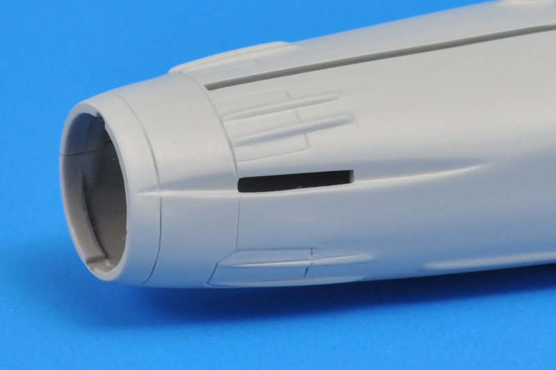
The latter was fairly easily solved by scribing a new circumferential panel line that cut the top speedbrakes shorter. This panel line also outlined the bare metal part of the rear fuselage. The front ends of all four speedbrakes were shortened with new panel lines. The remainder of the old speedbrake outlines was then filled with Apoxie.
|
| The result of the speedbrake modification after two coats of Mr Surfacer. This might be the last modification of the fuselage.
| 
|

| After the speedbrake modification, I could finally add the four tail feathers. I glued all of them from the inside of the fuselage, where the tabs were accessible to be covered in CA glue. On the exterior I used Apoxie to fill the gaps. The vertical tail and ventral fin were already painted, the horizontal tails are still bare plastic.
|
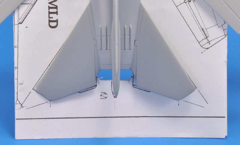
To check the horizontal tails, I scanned and printed the top view drawing from the 4+ booklet, and glued it on cardboard. The fuselage was cut out, so the template could slide it over the fuselage and under the tail planes. However, the Hasegawa fuselage was some 3 mm wider than the drawing, so more had to be cut from the cardboard.
The agreement was reasonable, too little deviation to modify the kit parts. The trim tabs should be added.
The accidental discovery that the kit's fuselage was too wide was a surprise. The 4+ drawing measures slightly over 22 mm just behind the wings. The model measures 25.3 mm, agreeing with the 3 mm that I had to additionally cut away from the template. The Hasegawa model is therefore a little fat!
| 
|

| A similar process was used to check the ventral fin. It too wasn't bad, but the span (height) was about 1 mm too large. The leading edge was missing a small bit of area too.
|
Only at this stage I read somewhere that the Hasegawa wing chord was too small. And indeed, compared to the 4+ drawing, 1.5 mm was missing at the root, and 1 mm at the tip. Although I had declared the wings ready, I decided to correct this after all. Luckily Hasegawa made the flap and aileron chords too short, so their hinge lines required no work, it was just a question of extending the trailing edge.
To have a bit more thickness to glue the extension on, I cut off 1 mm from the trailing edge. Next I added plastic strips, and lastly a 0.3 mm spring steel wire to create a solid and straight trailing edge. This was followed by some initial sanding. After this modification, I found Pierrig Salaün's 1/72 Hasegawa MiG-23MF Flogger-B article, that has a mostly similar wing modification.
| 
|

| As moulded, the wing sweep of the 'forward' position is ~5 degrees too little, as can be seen in the previous photo. I had to modify the wing's leading edge inside the glove wing (see next photo), to allow the wing to sweep to its most forward setting, where the trailing edges are perpendicular to the centerline.
Here's what the model looked at this stage. Work on the chord extension of the wings is not quite finished yet. But overall I'm happy with the progress of the model.
|
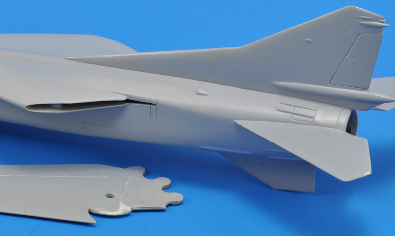
With the extended trailing edges, the wings could not be swept to the rearmost position, that should look 'overswept'. That overswept look is the result of the leading edge that was extended in the early phase of operational use.
I had to extend the slot in the rear fuselage by 2 mm to achieve the fully swept position. The circular part of the leading edge also had to be modified, because it was too short for the fully swept position.
| 
|
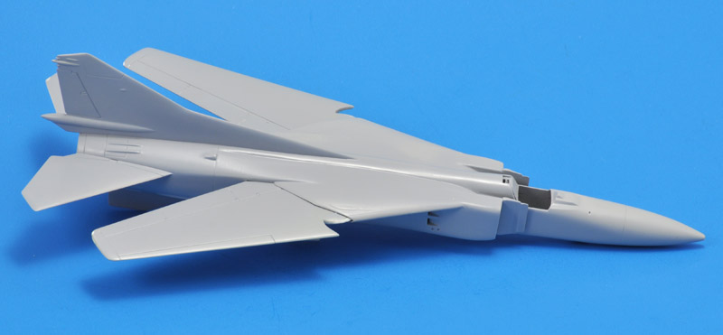
| The wings can now again be swept to the correct position.
|
| For the purposes I had in mind for the model, a pitot tube wouldn't survive. Therefore I installed a steel pin, sanded to a point. The Hasegawa model is behind the Airfix MiG-23.
| 
|
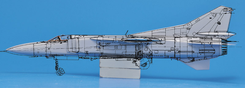
| To my eye, the model still didn't look like a MiG-23. One problem could be that the nose section is too horizontal. I made a near-perfect side view photo, and overlaid it with the 4+ MiG-23MF drawing. This confirmed my suspicion. The required drop of the tip of the radome is a measely 1.2 mm.
|
Construction is to be continued. Possibly, the modifications are not done yet. I still need to check the following:
glove wings: is the span correct? The glove wing is probably too thick; it's ~4 mm in the drawings
nozzle: diameter 15 mm (Aeroplan) or 14.5 mm (4+)
parachute container: diameter and length possibly too small
maybe the tail planes should be mounted about 1mm higher, right up to the upper speed brake
Markings
| From 1990 to 1994 we roamed the former East-Germany for Soviet / Russian military aircraft, that were being withdrawn during those years. This of course lead to all kinds of plans for building the aircraft we saw there. I bought two SuperScale decal sheets for that purpose: 72-572 'Russian numbers (current) solid color & outlined' and 72-573 'Russian stars (WWII to current) all styles'. I used quite a few of the stars, but the numbers were too generic. These decals are perfect for this project, since I'm building a generic MiG-23.
| 
|
Appendix 1: radome sizes for the MF, MS, ML and MLD
Having several drawing sets of the MiG-23 only complicates matters, since they don't agree. Just to start, I wanted to see the differences in the nose contours as depicted in the 4+ booklet.
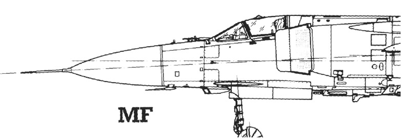
| The MF in black.
The nose is tilted down 2.5 degrees according to the drawing, but I'm not so sure of the horizontal reference line drawn through the fuselage. There are two, the one for the front fuselage is positioned lower than the one through the rear fuselage (not shown here). The latter also does not run through the middle of the rear fuselage, although it does line up with the nozzle.
Note that the canopy is tilted, something not seen in other drawings. At frame 12 (rear of the canopy hinge) I measure a height of 21.8 mm.
|
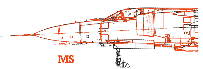
| The MF in black overlaid with the MS in red. The nose contour is identical, but of course the MS has a smaller radome, and subsequently an extra sheet metal section, but within the same contours.
|
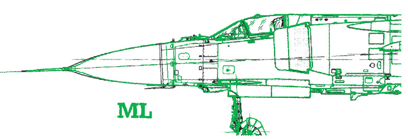
| The MF in black overlaid with the ML in green. The radome is shaped differently at the front, the pitot tube is a bit shorter, and the radome-nose division is further aft. Note that there are two 'radome lines', since the radome ends with a sheet metal section, that is connects to the fuselage (see Aeroplan p24).
|
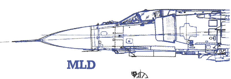
| The MF in black overlaid with the MLD in blue. The radome and pitot tube are identical. However, the MLD has small horizontal strakes at the transition from pitot tube to radome, to generate small vortices at high angles of attack.
|
Return to models page